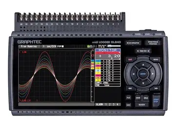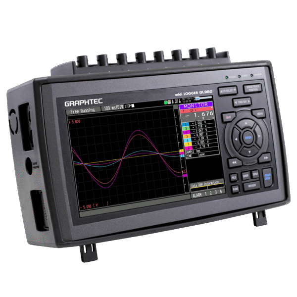
Description
All Channel Isolated / Universal Input, Standalone Multi-Channel
Voltage, temperature, and humidity can be selected for each input channel.
Use EU scaling for other measurement parameters.
Measure voltage
Supports wide operating range (from 20 mV to 100 V)
Measure temperature
Thermocouple: K, J, E, T, R, S, B, N, C(old W:WRe5-26)
RTD*: Pt100・JPt100・Pt1000(IEC751)
(only 3 wire type is supported)
*Please use B-565 for connecting the RTD
Measure current (4 -20 mA)
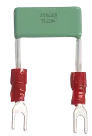
Shunt resistor (250Ω) is available as an option.
Equipped with a dedicated 1-5V range for the measurement range
Shunt resistance 250Ω (B-551)
*Cannot be used with the screwless terminal
Measure humidity
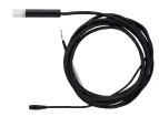
A humidity sensor is available as an option.
Power for the sensor is also supplied from the main unit.
Equipped with a dedicated humidity range
Humidity sensor (B-530)
Digital I/O port available
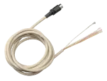
Digital I / O can be used by connecting an optional I / O cable.
Input/Output cable (B-513)
<Logic/Pulse inputs (4 channels)>
Logic: No-voltage contact (A contact, B contact, NO, NC) ,Open collector, Voltage input (H.L decision)
Pulse: 3 types of selections (Rotation / Quantity count / Instantaneous) per channel
<Alarm output: 4ch>
Alarm conditions can be set for each input channel.
Signal output from outputs 1 to 4 is possible in the event of an alarm.
Flexible Options with 4 Terminals
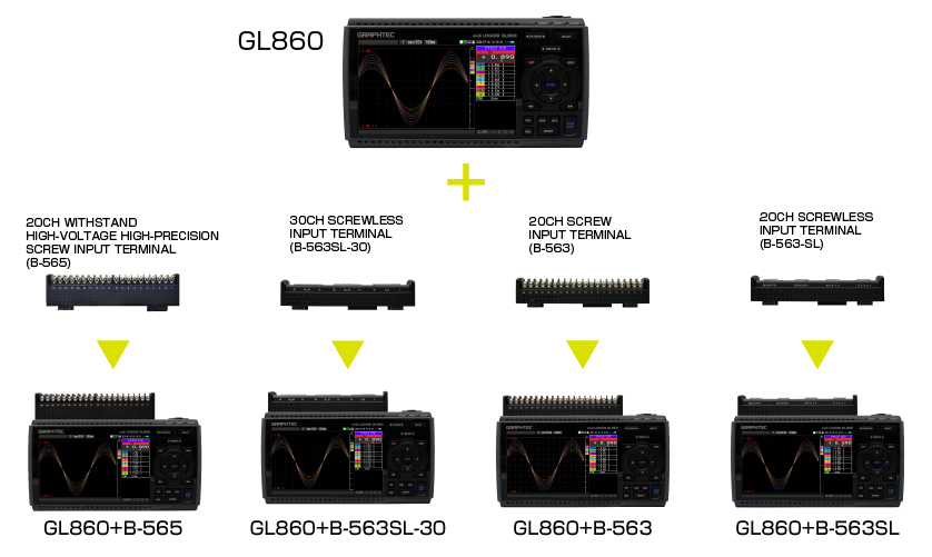
4 types of terminals including high withstand voltage B-565 are lined-up.
Select the terminal that best suits your measurement application.
Terminal Specification Comparison
 WITHSTAND HIGH-VOLTAGE HIGH-PRECISION TERMINAL (B-565) |
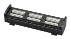 30CH SCREW LESS INPUT TERMINAL (B-563SL-30) |
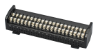 20CH SCREW INPUT TERMINAL (B-563) |
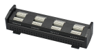 20CH SCREWLESS INPUT TERMINAL (B-563SL) |
|||||||
| Number of input channels | 20ch | 30ch | 20ch | 20ch | ||||||
| Input terminal type | M3 screw-type | Screwless | M3 screw-type | Screwless | ||||||
| Input method | Photo MOS relay scanning system All channels isolated, balanced input |
|||||||||
| Measurement ranges ※1 | Voltage | 20, 50, 100, 200, 500 mV, 1, 2, 5, 10, 20, 50, 100 V, 1-5 V F.S. | ||||||||
| Temperature | Thermocouples:K, J, E, T, R, S, B, N, C (W: WRe5-26) | |||||||||
| RTD (only 3 wire type is supported) : Pt100, JPt100, Pt1000(IEC751) | (* RTD cannot be connected.) | |||||||||
| Temperature range: 100°C, 500°C, 2000°C (In the case of Fahrenheit: 150°F, 750°F, 3000°F) | ||||||||||
| Humidity | 0 to 100% (Optional humidity sensor B-530 is required) | |||||||||
| Maximum permissible input voltage | Between +/– terminals | 20mV to 2V range (60Vp-p) 5V to 100V range (110Vp-p) |
||||||||
| Between input terminal/input terminal | 600Vp-p | 60Vp-p | ||||||||
| Between input terminal/GND | 300Vp-p | 60Vp-p | ||||||||
| Withstand voltage | Between input terminal/input terminal | 600Vp-p | 350Vp-p 1 minute | |||||||
| Between input terminal/GND | 2300VACrms 1 minute | 350Vp-p 1 minute | ||||||||
| Voltage measurement accuracy | ±(0.05%ofF.S.+10μV) | ±0.1% of F.S. | ||||||||
| Operating environment | 0 to 45℃ | |||||||||
| Dimensions(*including GL860) | 240×166×52.5mm (exclude protrusion) | 240×158×52.5mm (exclude protrusion) | ||||||||
| Weight(*including GL860) | 1035g (exclude AC adapter & battery) | 1010g(exclude AC adapter & battery) | ||||||||
*Please refer to the user manual for the measurement accuracy of each terminal.
Maximum input voltage
B-565
< Between +/– terminals (A) >
– Maximum input voltage: 60Vp-p (Range of 20mV to 2V)
110Vp-p (Range of 5V to 100V)
< Between input terminal/input terminal (B) >
– Maximum input voltage: 600Vp-p
– Withstand voltage: 600Vp-p
< Between input terminal/GND (C) >
– Maximum input voltage: 300Vp-p
– Withstand voltage: 2300Vp-p at 1 minute
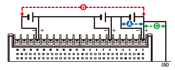
B-563SL-30 / B-563 / B-563SL
< Between +/– terminals (A) >
– Maximum input voltage: 60Vp-p (Range of 20mV to 2V)
110Vp-p (Range of 5V to 100V)
< Between input terminal/input terminal (B) >
– Maximum input voltage: 60Vp-p
– Withstand voltage: 350Vp-p at 1 minute
< Between input terminal/GND (C) >
– Maximum input voltage: 60Vp-p
– Withstand voltage: 350Vp-p at 1 minute
Channel Expansion of Analog Signal Input Port
Expandable up to 200 channels.
Example
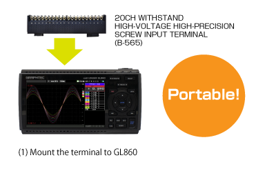
20ch / 30ch
40ch or more (up to 200ch)
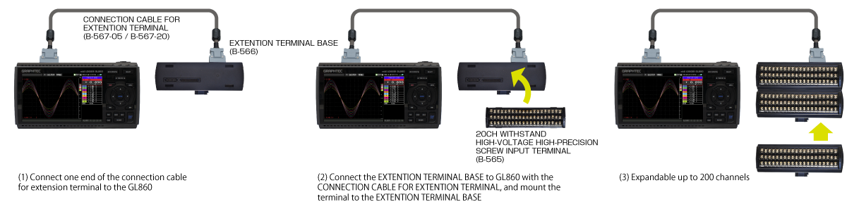
Example of channel expansion
| Number of channels | 20ch | 30ch | 40ch | 50ch | 100ch | 200ch |
| GL860 | 1 | 1 | 1 | 1 | 1 | 1 |
| Connection cable for extension terminal (B-567-05/B-567-20) |
– | – | 1 | 1 | 1 | 1 |
| Base unit for input terminal (B-566) |
– | – | 2 | 2 | 4 | 7 |
| 20ch terminal*1 (B-565/B-563/B-563SL) |
1 | – | 2 | 1 | 2 | 1 |
| 30ch terminal*1 (B-563SL-30) |
– | 1 | – | 1 | 2 | 6 |
*1. When using B-565 with other terminals,
Withstand voltage: lower withstand voltage will be applied
Accuracy: depends on the terminal
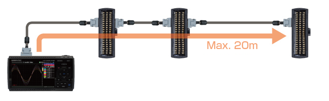
The input terminal and GL860 can be extended by using the connection cable for extension terminal (50cm / 2m)
*If the measurement is affected by noise, slow down the sampling interval.
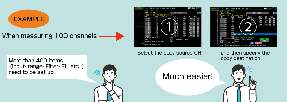
CH copy function is useful for multi-channel measurements
Copy settings such as input, range, filter, EU, etc. at once.
The setup can be done simply by selecting a channel, greatly reducing the man-hours required.
Trigger and alarm settings can also be copied
Maximum Sampling Interval of Up to 5ms
Up to 5ms sampling speed is achievable when limiting the number of channels in use.
| Sampling Interval | 5ms | 10ms | 20ms | 50ms | 100ms | 250ms | 500ms | 1s | |
| Number of channels | 1 | 2 | 4 | 10 | 20 | 50 | 100 | 200 | |
| Measuring | Voltage / Humidity | ● | ● | ● | ● | ● | ● | ● | ● |
| Temperature | – | – | – | – | ● | ● | ● | ● | |
Built-in 8GB Flash Memory with SD Card Support
Example of recording time (data size: 2GB)
| Sampling Interval | 5ms | 10ms | 50ms | 100ms | 200ms | 500ms | 1s | 10s |
| GBD format | 15 days | 24 days | 47 days | 54 days | 108 days | 270 days | 366+ days | 366+ days |
| CSV format | 1 day | 3 days | 8 days | 11 days | 22 days | 55 days | 111 days | 366+ days |
*Figures are approximate. File size of captured data is 2GB in GBD or CSV file format on this chart.
5ms: 1ch, 10ms: 2ch, 20ms: 4ch, 50ms: 10ch
Ring capture function

The most recent data is saved when the memory is configured in ring memory mode. (Number of capturing data is 1000 to 2000000 points)
Relay capture function
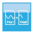
Data is continuously saved to multiple files up to 2GB without losing any data until capturing is stopped when the memory is configured in the relay mode.
Memory loop function
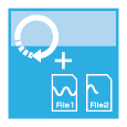
In addition to the existing relay capture function, the oldest file is automatically deleted before memory capacity runs out.
Hot-swapping the SD memory card
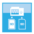
SD card can be replaced during data capturing when the sampling interval is 100ms or slower.
*When the wireless LAN is installed, the SD memory card cannot be inserted into the SD CARD slot.
Back up recording data
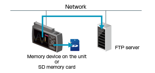
The data file can be created periodically for purpose of backing up data while recording it, and the file is automatically transferred to another storage device on the unit or FTP server on the network.
Backup interval: 1, 2, 6, 12, 24 hour(s)
Backup file destination: SD memory card or FTP server
Data file format: GBD (binary) or CSV (text)
- The CSV format is available with firmware version 1.43 or rater.
• Available sampling speed is the 100 ms or slower when using the CSV format.
• When the RING mode or external pulse synchronization sampling is selected for recording, the backup function is not available.
• The storage device specified as the recording destination of the measurement data can not be set as the transfer destination of the backup file.
• When backup is enabled and data file format is specified with CSV format, SD memory card exchange (hot-swapping) and RELAY recording are not available.
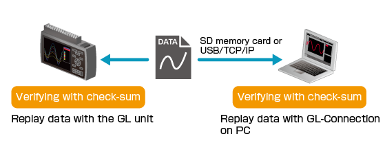
Data file verification
It is a function to check the integrity of the data file when replaying the data file. It compares check-sum generated from the data file and recorded check-sum. When two check-sums do not match, the data file may be corrupted or has been changed by someone. The check-sum code is recorded into the file when data file is created by the GL unit.
- Check-sum code is added to normal data recording file and also file created for backup, ring or relay recording. Adding check-sum is available for data files created in GBD format. When the recorded data file is converted and saved using GL100_240_840-APS or GL-Connection software, the check-sum code will not match.
- This function is available with firmware version 1.43 or rater.
Multiple PC Interfaces Depending on Measurement Environment
Connection to your PC can be made via USB, wireless LAN or wired LAN.
*Optional B-568 is required for wireless LAN connection. The USB connection is a common A-B type cable.
Wireless connection with PC using Optional Wireless LAN unit (B-568)
*Optional Wireless LAN unit is available in limited region.
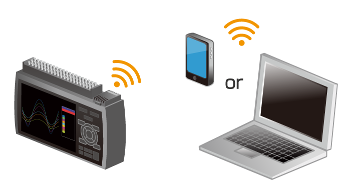
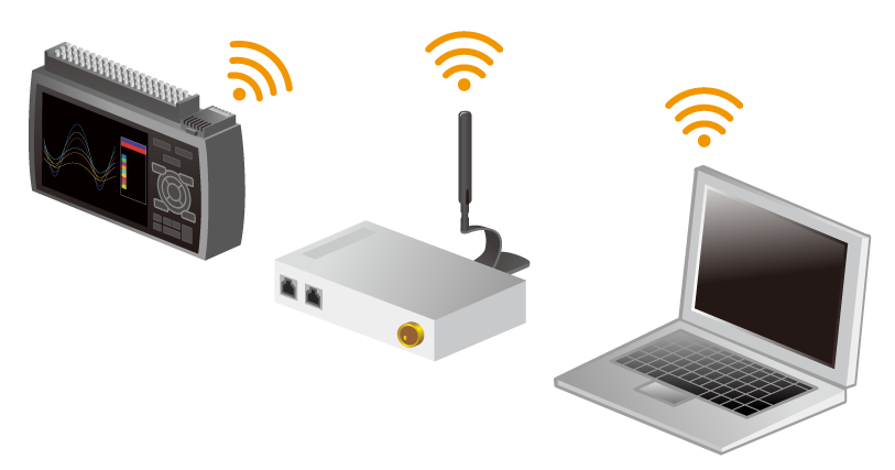
Wireless LAN option enables the wireless communication with the other devices.
Access Point enables direct connection to PCs and smart devices without a router.
Station enables connection to a wireless LAN router. Depending on the environment, data can be checked and e-mails can be received with remote PCs and smart devices via the Internet.
Wired connection with PC by Ethernet (10BASE-T / 100BASE-TX)
One-to-one connection with a PC or multiple connections via a HUB are possible.